
 English
 русский
 Español
 عربى
عربى

Content
- 1 Rubber Compression Molding Machine: The Direct Answer Before the Detail
- 2 Tonnage and Platen Specifications at a Glance
- 3 Core Components That Determine Machine Reliability
- 4 How a Compression Molding Cycle Actually Runs
- 5 Automation and Control System Trends
- 6 Compression Molding Machine vs. Rubber Extrusion Production Line
- 7 Matching Rubber Compounds to Molding Conditions
- 8 Working Out the Tonnage a Job Actually Needs
- 9 Common Molding Defects and Their Press-Side Fixes
- 10 Operating Cost Factors Beyond the Purchase Price
- 11 Running a Press and a Rubber Extrusion Production Line Together
- 12 Maintenance Habits That Extend Machine Life
- 13 Questions to Settle Before Placing an Order
- 14 Frequently Asked Questions
- 14.1 How long does a rubber compression molding machine typically last?
- 14.2 Can one machine switch between multiple rubber compounds?
- 14.3 Is a compression molding machine or a Rubber extrusion production line the better first investment for a new plant?
- 14.4 What causes flash lines that will not trim cleanly?
- 14.5 How much does cycle time vary between compounds at the same wall thickness?
- 14.6 Does a bigger press always mean better part quality?
- 14.7 What is the most overlooked maintenance item on these machines?
- 14.8 How does multi-cavity tooling change tonnage requirements?
- 14.9 Can an existing compression molding press be retrofitted with better controls?
Rubber Compression Molding Machine: The Direct Answer Before the Detail
A rubber compression molding machine is a hydraulic or mechanical press that closes a heated mold around a pre-weighed rubber charge, holds it under pressure while the compound cures, then opens to release a finished part. Tonnage on commercial units generally spans 5 to 3,000 tons, platen sizes range from a few inches to more than 14 feet, and cycle times for a typical seal or gasket run between 3 and 12 minutes depending on wall thickness and cure chemistry. For buyers weighing a standalone press against a full Rubber extrusion production line, the short version is this: compression molding suits parts with complex three-dimensional geometry, while an extrusion line is the better fit for continuous profiles, hoses, and seals sold by the meter. Many plants run both side by side, feeding the same mixed compound into a press for molded parts and into an extruder for profile stock.
The remainder of this guide works through tonnage selection, machine components, the molding cycle itself, automation and control trends, how compression molding compares with a Rubber extrusion production line on cost and output, compound selection, defect troubleshooting, operating cost, hybrid production line planning, and the maintenance habits that keep a press earning its keep for fifteen years or longer. Each section is written to stand on its own, so a buyer evaluating a single quote can jump straight to the relevant table, while a plant manager building a full production plan can read the piece end to end.
Tonnage and Platen Specifications at a Glance
Press builders size a rubber compression molding machine around three numbers: clamping tonnage, platen daylight, and closing speed. A small lab press might clamp at 10 tons with an 8-inch by 8-inch platen, while a production unit serving automotive body seals or large industrial gaskets can run past 500 tons with platens exceeding four feet on a side. The table below summarizes typical ranges seen across current machine catalogs from press builders in North America, Europe, and China.
| Machine Tier | Clamping Tonnage | Platen Size | Daylight Opening | Typical Use |
|---|---|---|---|---|
| Lab / Prototype | 5–25 tons | 8" x 8" to 12" x 12" | 6"–12" | R&D, small O-rings, sample runs |
| Light Production | 25–100 tons | 12" x 12" to 18" x 18" | 12"–20" | Grommets, small gaskets, bushings |
| Standard Production | 100–500 tons | 18" x 18" to 36" x 36" | 18"–30" | Automotive seals, industrial mounts |
| Heavy Production | 500–3,000 tons | 36" x 36" to 14 feet | 30"–60" | Large panels, marine fenders, multi-cavity molds |
Closing speed matters as much as tonnage. Fast-closing presses move at 200 to 300 inches per minute until the mold nears contact, then slow sharply to protect the tool and avoid trapping air in the cavity. Hydraulic pressure on most modern presses tops out near 3,000 psi, and platen heating is supplied by electric cartridge heaters, circulating oil, or steam, with electric heating now the most common choice for new installations because of tighter temperature control and simpler wiring.
Frame Styles and When Each One Makes Sense
Frame design changes how a press handles side loading and how easily an operator can access the mold for changeovers. Four-post presses use high-tensile guide rods with square-shouldered crossheads to keep the platens parallel through the full stroke, and they remain the default choice for general-purpose production because they are simple to maintain and forgiving of slightly off-center loading. C-frame presses trade some rigidity for open-sided access, which speeds up mold changes on plants that run many short jobs. Window-frame and side-plate presses appear on heavier, purpose-built lines where a single large mold runs for extended periods and side access is less important than raw rigidity across a wide platen.
Heating Method Trade-Offs
Electric cartridge heating gives the fastest warm-up and the most even zone-by-zone control, which is why most new press installations specify it by default. Oil heating spreads temperature very evenly across a large platen and tolerates rougher plant environments, making it a common choice on older heavy-production presses that were designed before electric zone control became standard. Steam heating is efficient up to roughly 360 degrees Fahrenheit at 150 psi and remains common in plants that already run a steam boiler for other equipment, since the marginal cost of adding a press to that loop is low.
Core Components That Determine Machine Reliability
Every rubber compression molding machine is built around the same functional blocks, and the quality of each one directly affects scrap rate and uptime.
- Hydraulic Power Unit — the pump, motor, and valve bank that generate and regulate clamping force. Variable-speed pumps cut energy draw during the dwell phase when full pressure is already established.
- Platens — machined steel plates, ground flat and parallel, that carry the mold halves and the heating elements. Warped or unevenly heated platens are the single most common cause of flash and short shots.
- Guide Columns and Bushings — four-post or C-frame guides that keep the moving platen square to the fixed platen through thousands of cycles, protecting mold alignment.
- Temperature Control System — electric, oil, or steam heating with closed-loop controllers holding platen temperature within roughly plus or minus 2 degrees Celsius, which is critical for consistent cure state.
- Control Processor and Interface — the programmable logic controller and touchscreen or panel that store cure recipes, log cycle counts, and trigger safety interlocks.
- Safety Guarding — light curtains, two-hand controls, and mechanical shot pins that keep operators clear of the closing platens.
- Ejection System — mechanical knockout pins or an air-assisted ejection plate that releases the cured part from the lower mold half without tearing thin sections.
- Vacuum Ports — on presses built for tight-tolerance or bubble-sensitive parts, vacuum drawn on the cavity just before final closing pulls air out ahead of the rubber flow front, reducing porosity on complex geometries.
Bolsters, the intermediate steel plates that mold tooling bolts to, are machined flat and ground parallel, and on higher-end presses they include temperature-compensating guide sleeves that hold clearance steady even as the steel expands during a long production run. This detail rarely appears on a spec sheet headline, but it has an outsized effect on how consistently a mold seats cycle after cycle once a press has been running for several hours.
How a Compression Molding Cycle Actually Runs
Understanding the cycle helps a buyer judge whether quoted cycle times are realistic for a given part.
- A weighed rubber preform, or in some cases raw slab stock, is placed into the open, heated cavity.
- The press closes at high speed until the platens near contact, then slows to a controlled crawl so trapped air can escape through vents before final tonnage is applied.
- Full clamping pressure is held for the dwell time set by the cure recipe, during which the crosslinking reaction that turns pliable rubber into a rigid, elastic solid takes place.
- The press opens, the part is ejected by pins or manually with a hook, and any flash line is inspected before the part moves to trimming.
- Many plants run a post-cure oven step afterward for compounds such as silicone that need additional time to drive off cure byproducts and reach full mechanical properties.
Why Preform Shape Changes Fill Quality
A preform cut to roughly match the cavity's cross-section fills more evenly than a simple slug dropped in the center, because the rubber has less distance to flow before reaching the cavity extremities. Long, thin flow paths increase the odds of trapped air and knit lines where two flow fronts meet, so mold designers often shape the preform, or split it into multiple smaller pieces positioned across the cavity, specifically to shorten those flow distances.
Reading a Press Cycle Timer Correctly
A quoted cycle time usually covers close, dwell, and open, but not the preform loading and part removal steps that happen with the press open. On a manual cell those steps can add 15 to 30 seconds per cycle, while an automated loading arm or a multi-station rotary table keeps that overhead close to zero by preparing the next preform while the previous part is still curing.
Automation and Control System Trends
Modern rubber compression molding machines are increasingly specified with programmable logic controllers paired with touchscreen interfaces that store dozens of cure recipes, so an operator selects a job number rather than manually dialing in temperature and dwell each time a mold changes. This reduces the chance of running the wrong cure profile on a new job, which is one of the more common causes of an entire batch of scrap.
- Recipe storage keeps temperature, dwell time, and closing speed tied to a specific mold or part number, cutting setup error on job changeovers.
- Cycle counters and data logging track how many shots a given mold has run, which supports planned tooling maintenance instead of reactive repairs after a defect appears.
- Closed-loop pressure control uses a proportional valve and pressure transducer to hold ram force steady through the dwell phase rather than relying on the pump simply staying at full output.
- Remote monitoring dashboards increasingly let a maintenance team watch platen temperature trends and hydraulic pressure across an entire press bank from one screen, flagging drift before it produces a defect.
- Automated loading and unloading, whether a simple pick-and-place arm or a rotary multi-station table, removes the operator-dependent portion of cycle time and improves shift-to-shift consistency.
None of this automation replaces the fundamentals of mold design and compound selection, but it narrows the gap between a well-run first shift and a less experienced weekend crew, which matters most in plants running three shifts with rotating staff.
Compression Molding Machine vs. Rubber Extrusion Production Line
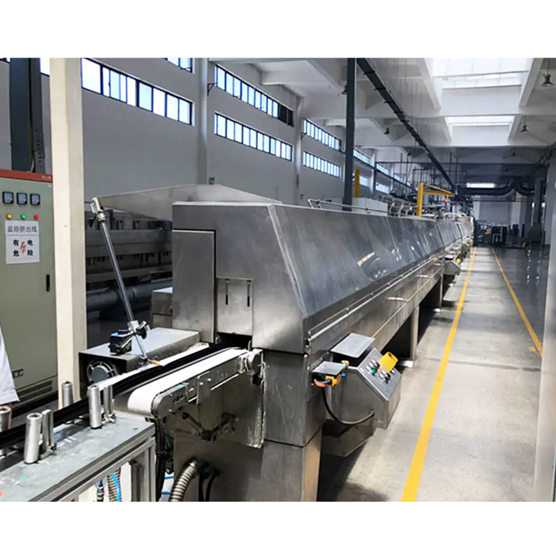
The two processes are often confused by buyers new to rubber manufacturing, but they solve different geometry problems. A compression molding machine produces discrete, often complex parts one mold cycle at a time. A Rubber extrusion production line, by contrast, forces uncured rubber continuously through a die to create a profile with a constant cross-section, such as a weatherstrip, hose, or cable jacket, which is then cured in a continuous vulcanizing line rather than a closed mold.
| Factor | Compression Molding Machine | Rubber Extrusion Production Line |
|---|---|---|
| Best part geometry | Three-dimensional, closed-cavity parts | Constant cross-section profiles |
| Output measured in | Parts per cycle | Meters per minute |
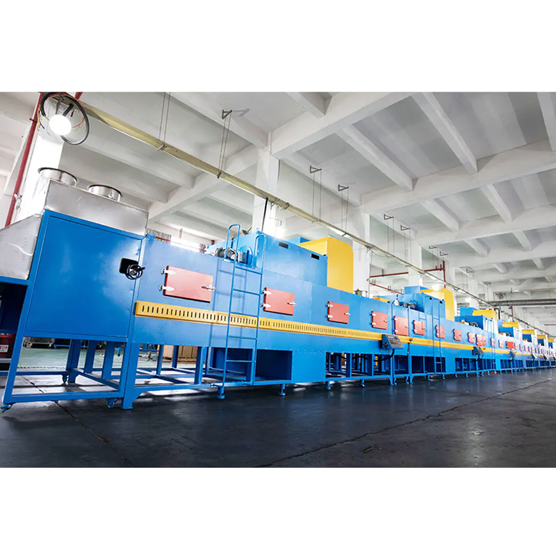
| Curing method | Heated closed mold, dwell time | Continuous vulcanizing box, microwave, or autoclave |
| Tooling cost | Higher per cavity, dedicated mold | Lower per profile, reusable die |
| Typical products | Gaskets, mounts, O-rings, bushings | Seals, hoses, weatherstrips, tubing |
| Changeover time | Minutes to swap a mold on a compatible press | Longer, since die and vulcanizing zone settings both shift |
| Feed preparation | Pre-weighed preform or slab charge | Continuous strip, slab, or pellet feed |
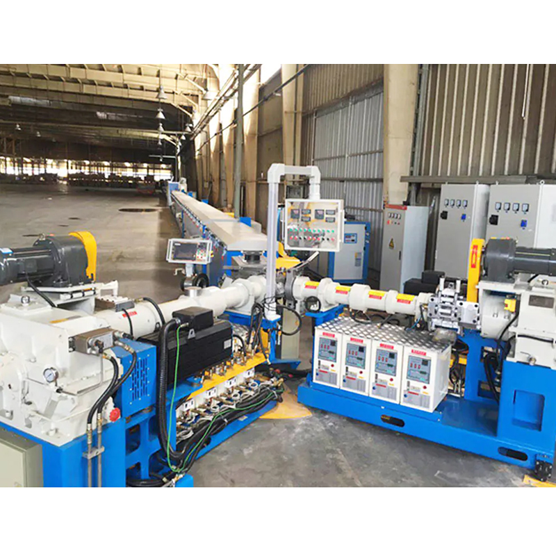
A Rubber extrusion production line is usually built around either a hot feed or a cold feed extruder. Hot feed lines take rubber that has already been warmed and masticated on a two-roll mill, which suits simple, large-section profiles and keeps initial equipment cost lower. Cold feed lines accept rubber strip or pellets at room temperature and generate the necessary heat internally through a longer screw and barrel, which gives tighter dimensional tolerance and higher throughput once the line is running. Industry equipment tracking for 2026 shows cold feed systems now account for roughly 61 percent of the rubber extrusion machines market by value, with hot feed systems holding close to 39 percent, largely because cold feed lines cut labor and improve consistency on long production runs.
Where the Two Processes Meet
Some parts do not fit neatly into either category. A gasket cut from a long extruded profile, for example, starts on a Rubber extrusion production line and finishes as a discrete part once it is cut to length and its ends are joined or molded closed, sometimes on a small compression press fitted with a splice mold. Buyers scoping a new product line should map the finished part's geometry against both processes before committing capital to only one.
Matching Rubber Compounds to Molding Conditions
The compound selected changes cure temperature, dwell time, and mold release behavior, all of which feed back into how a machine's control recipe should be programmed.
| Compound | Typical Cure Temp | Common Applications | Notes |
|---|---|---|---|
| Natural Rubber (NR) | 140–160 °C | Vibration mounts, bumpers | High resilience, low heat resistance |
| EPDM | 150–180 °C | Weatherstrips, outdoor seals | Strong resistance to ozone and weathering |
| NBR (Nitrile) | 150–170 °C | Fuel and oil seals, gaskets | Good oil resistance, moderate cold flexibility |
| Silicone (VMQ) | 165–190 °C | Medical, food-contact, high-heat seals | Often needs a secondary post-cure oven cycle |
| Chloroprene (CR) | 150–170 °C | Marine fenders, gaskets exposed to weather | Balanced weather and oil resistance |
| FKM (Fluoroelastomer) | 170–200 °C | High-temperature seals, chemical exposure parts | Higher material cost, excellent chemical resistance |
Wall thickness drives dwell time more than any other single variable, since heat has to travel from the mold surface to the geometric center of the rubber mass before the entire section reaches cure temperature. A thin gasket may need only 90 seconds of dwell, while a thick mount or block can require ten minutes or more even on a well-heated platen.
Hardness, Compression Set, and Why They Matter to Press Setup
Compound hardness, expressed on the Shore A scale, affects how much clamping pressure is needed to fully close a mold, with harder compounds generally requiring somewhat higher tonnage per unit of projected area to avoid short shots. Compression set, the tendency of a cured part to stay compressed rather than spring back after a load is removed, is influenced heavily by cure state, so under-curing a part to save cycle time often shows up later as a compression set failure in the field rather than as an obvious defect at the press.
Working Out the Tonnage a Job Actually Needs
Under-sizing a press causes flash and incomplete fill; over-sizing wastes capital and energy on every cycle. A commonly used starting formula for required clamping tonnage is:
Required tonnage = projected part width x projected part length x 2,000 pounds x 0.0005, with width and length measured in the same unit and the result expressed in tons.
For example, a rectangular gasket measuring 10 inches by 8 inches gives 10 x 8 x 2,000 x 0.0005, or 80 tons of minimum clamping force. Press builders typically recommend adding a safety margin of 15 to 25 percent above the calculated figure to account for multi-cavity molds, compound hardness, and flash-control pressure, so an 80-ton calculated load often points a buyer toward a 100-ton press in practice.
| Part Footprint | Calculated Tonnage | Recommended Press Size (with margin) |
|---|---|---|
| 4" x 4" | 16 tons | 25 tons |
| 10" x 8" | 80 tons | 100 tons |
| 18" x 18" | 324 tons | 400 tons |
| 36" x 24" | 864 tons | 1,000 tons |
Multi-cavity tooling multiplies this figure by the number of cavities being filled simultaneously, which is why a single production mold with sixteen small O-ring cavities can demand as much tonnage as one large industrial mount. When a mold mixes cavity sizes, the calculation should sum the projected area of every cavity rather than simply multiplying the largest cavity by the cavity count, since that shortcut tends to oversize the press unnecessarily.
Common Molding Defects and Their Press-Side Fixes
Most defects that show up on a finished rubber part trace back to one of three sources: the mold, the compound, or the press settings. Sorting a defect into the right category before making a change saves a lot of wasted trial and error on the shop floor.
| Defect | Likely Cause | First Corrective Step |
|---|---|---|
| Flash | Excess preform charge, worn parting line, low clamping tonnage | Trim preform weight, inspect mold parting line, confirm tonnage against the calculated requirement |
| Short shot | Insufficient material charge, blocked vents, premature partial cure | Increase preform weight, clear vent channels, check preform storage temperature |
| Porosity or blisters | Trapped air, moisture in compound, poor venting | Improve mold venting, extend hold time slightly, verify compound storage conditions |
| Surface burn | Platen temperature too high for the compound, extended dwell | Reduce set temperature toward the compound's recommended range, re-check dwell time |
| Dimensional drift | Platen parallelism loss, mold wear, temperature non-uniformity | Check platen parallelism, inspect mold wear points, verify heater zone calibration |
| Poor compression set in service | Under-cure, wrong dwell time for wall thickness | Extend dwell time and re-check cure state before assuming a material problem |
Because several of these defects share overlapping symptoms, many plants keep a simple first-shot inspection routine after any mold or recipe change, checking flash line thickness, cavity fill completeness, and surface appearance before releasing a full production run.
Operating Cost Factors Beyond the Purchase Price
The sticker price of a rubber compression molding machine is only part of its total cost over a working life that can exceed fifteen years. Four recurring cost categories tend to matter most once a press is in daily use.
- Energy use during dwell is largely a function of platen heating method and how well insulated the platens are, since most of a cycle's energy draw happens holding temperature rather than during the brief closing motion.
- Hydraulic fluid and filtration replacement follows a fixed schedule regardless of how many parts a press produces, so higher-utilization presses spread this cost over more output and post a lower per-part fluid cost.
- Mold wear and refurbishment scales with cycle count and compound abrasiveness, and is one of the clearer arguments for automated cycle logging discussed earlier in this guide.
- Scrap rate tied to flash, short shots, or porosity is frequently the largest hidden cost on an older or poorly calibrated press, often outweighing energy and fluid costs combined on presses running high-value compounds such as silicone or FKM.
A useful exercise when comparing two press quotes at similar tonnage is to ask each vendor for expected energy draw per cycle at typical dwell time, rather than comparing nameplate motor horsepower alone, since actual draw during dwell is what shows up on the plant's utility bill.
Running a Press and a Rubber Extrusion Production Line Together
Plants that manufacture both molded parts and profile products frequently share upstream equipment between a compression molding machine and a Rubber extrusion production line. The same internal mixer and two-roll mill that prepare a compound batch for the press can feed strip stock to the extruder, so the mixing room becomes the shared hub for both processes.
- Shared compound batching reduces the number of separate mixing recipes a plant has to validate and store.
- Staggered scheduling lets a single mill supply both a press and an extruder across a shift without idle time on either machine.
- Common quality checks, such as durometer and specific gravity testing, apply to output from both the mold and the extrusion die, simplifying quality control staffing.
- Splicing equipment on the extrusion side keeps a continuous feed of rubber strip moving into the extruder as one stock pallet runs out and the next begins, which keeps line speed steady in a way a compression press cycle does not need to match.
The global rubber extrusion machines market was valued near 1.92 billion US dollars in 2026 and is projected to grow to roughly 2.88 billion dollars by 2035, according to industry equipment market tracking, with tire component production remaining the largest single application segment and industrial products such as seals, tubing, and weather strips making up close to a third of overall demand. That growth trajectory is a useful signal for plants deciding whether to add extrusion capacity alongside an existing compression molding line rather than treating the two processes as unrelated investments.
Sequencing a Combined Investment
Plants adding a Rubber extrusion production line to an existing compression molding operation generally see the smoothest transition when the mixing room is upgraded first, since both processes depend on consistent, well-dispersed compound. Extrusion die design and vulcanizing box length can then be specified around the actual profiles being targeted, rather than guessed at before the compound supply chain is settled.
Maintenance Habits That Extend Machine Life
- Check platen parallelism on a fixed schedule, since even a few thousandths of an inch of drift produces uneven flash across a multi-cavity mold.
- Filter hydraulic fluid on the interval the pump manufacturer specifies rather than waiting for a pressure drop to appear on the gauge.
- Verify heater zone temperatures against an independent probe every few months, because a drifting thermocouple can silently under-cure parts long before a visible defect shows up.
- Inspect guide columns and bushings for wear that would let the moving platen rock slightly off square during closing.
- Keep vent channels in the mold clear of built-up flash, since blocked vents trap air and cause porosity that looks like a material problem but is actually a tooling issue.
- Log cycle counts per mold so tooling refurbishment is scheduled by actual use rather than by calendar guesswork.
- Rotate and inspect ejection pins for wear, since a sticking pin can tear thin part sections during release even when everything else about the cycle is correct.
- Review hydraulic hose and seal condition on a fixed calendar interval, since a slow leak often shows up first as a slight tonnage drift rather than as a visible drip.
Frequently Asked Questions
How long does a rubber compression molding machine typically last?
A well-maintained hydraulic press with steel platens and a properly filtered hydraulic system regularly runs for fifteen to twenty-five years, with the hydraulic power unit and control electronics being the parts most likely to need mid-life replacement.
Can one machine switch between multiple rubber compounds?
Yes. The mold and heating recipe change per job, not the press itself, so a single machine can run natural rubber one shift and a silicone compound the next as long as the control system stores separate temperature and dwell profiles for each recipe.
Is a compression molding machine or a Rubber extrusion production line the better first investment for a new plant?
That depends on the target product line. A plant focused on discrete parts such as gaskets, mounts, or bushings should prioritize the press, while a plant targeting continuous profiles such as seals or hose should prioritize the extrusion line. Many mid-size manufacturers eventually invest in both once volume across either product family justifies dedicated equipment.
What causes flash lines that will not trim cleanly?
Persistent heavy flash is almost always tied to insufficient clamping tonnage for the part's projected area, worn mold parting lines, or platens that have lost parallelism, rather than the rubber compound itself.
How much does cycle time vary between compounds at the same wall thickness?
Silicone compounds generally need a longer dwell and an added post-cure oven step compared with NBR or EPDM at the same thickness, since silicone crosslinking chemistry and heat transfer characteristics differ from sulfur-cured general-purpose rubbers.
Does a bigger press always mean better part quality?
No. Once tonnage clears the calculated requirement with an appropriate safety margin, further increases mainly add cost and energy draw without improving part quality, and can even make fine flash control harder on very small parts run in an oversized press.
What is the most overlooked maintenance item on these machines?
Platen parallelism and heater zone calibration are checked far less often than hydraulic fluid, yet drift in either one produces the same flash and dimensional defects that get blamed on the compound or the mold.
How does multi-cavity tooling change tonnage requirements?
Tonnage should scale with the total projected area of every cavity filled at once, not just the largest single cavity, since each cavity contributes its own resistance to mold closing during the fill and pack stage.
Can an existing compression molding press be retrofitted with better controls?
In many cases yes. Replacing an older relay-based control panel with a modern programmable logic controller and touchscreen interface is a common mid-life upgrade that adds recipe storage and cycle logging without replacing the hydraulic frame itself.

