English
 русский
 Español
 عربى
عربى

Content
- 1 What Is a Rubber Kneader and How Is It Structured
- 2 The Mixing Chamber: The Heart of the Rubber Kneader
- 3 Rotors: The Defining Component of Rubber Kneader Design
- 4 The Hydraulic Ram (Floating Weight): Pressure Control Above the Compound
- 5 Discharge Door Mechanism: Releasing the Mixed Batch
- 6 Temperature Control System: Managing Heat Throughout the Rubber Kneader
- 7 Drive System: Power Transmission to the Rotors
- 8 Feed Throat and Charging System
- 9 Machine Frame and Structural Components
- 10 Control System and Instrumentation in Modern Rubber Kneaders
- 11 Key Structural Differences Between Rubber Kneader Types
- 12 Wear Parts and Maintenance-Critical Structural Elements
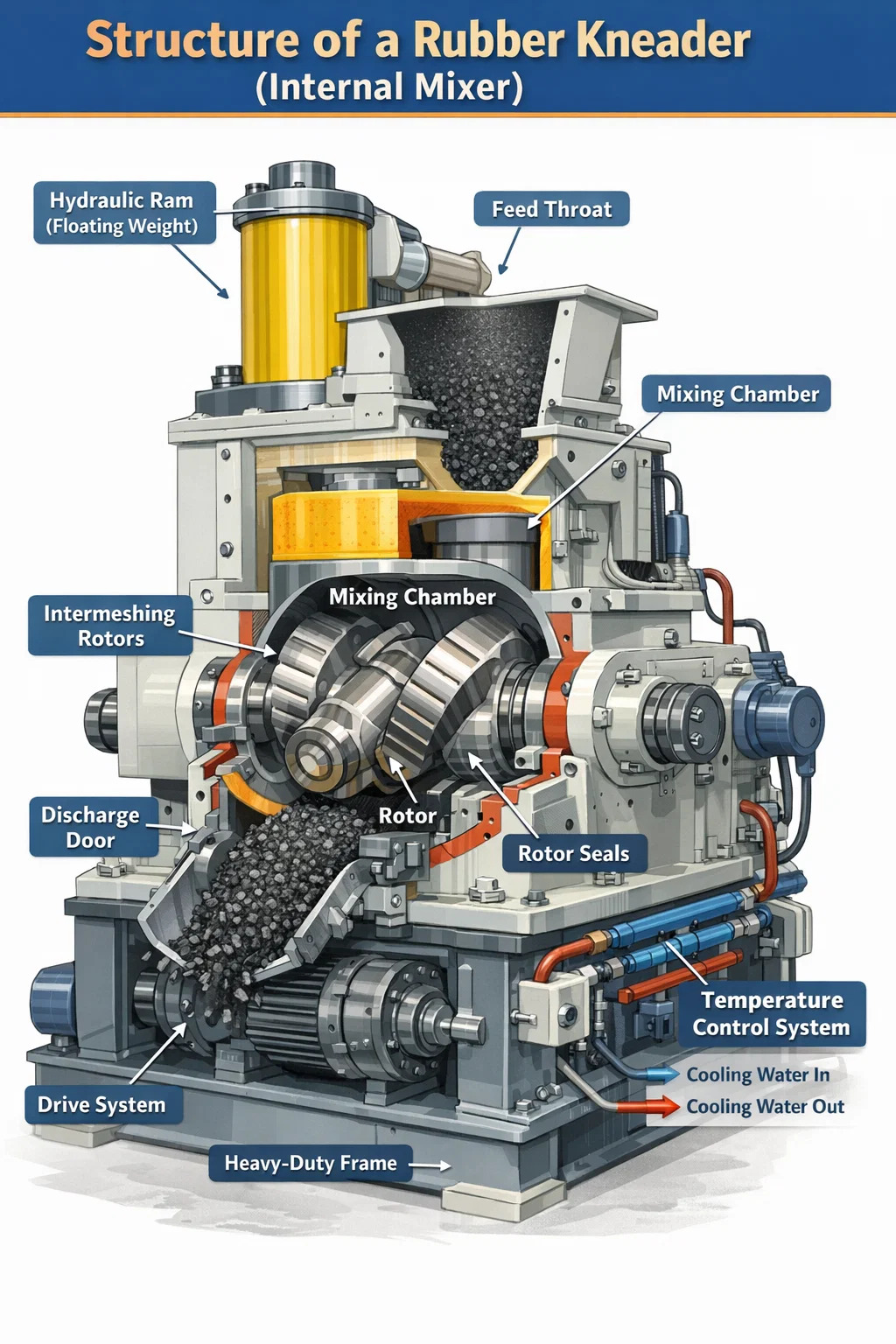
What Is a Rubber Kneader and How Is It Structured
A rubber kneader — also referred to as an internal mixer or banbury-type kneader — is a closed, high-intensity mixing machine used to compound raw rubber with additives such as carbon black, sulfur, accelerators, plasticizers, and processing oils. Unlike open mills, the rubber kneader performs mixing inside a sealed chamber, which dramatically reduces material loss, improves dispersion uniformity, and allows processing of temperature-sensitive compounds.
The core structure of a rubber kneader consists of six primary systems: the mixing chamber, the rotors, the hydraulic ram (floating weight), the discharge door mechanism, the temperature control system, and the drive system. Each plays a distinct mechanical role, and understanding how they interact reveals why internal kneaders have become the industry standard for rubber compounding in tire manufacturing, seals, gaskets, hoses, and technical rubber goods.
The machine body itself is typically constructed from high-strength cast steel or fabricated steel plate, with internal surfaces hardened or lined with wear-resistant alloy to withstand the enormous mechanical forces generated during mixing — often exceeding 500 kN in large-capacity machines.
The Mixing Chamber: The Heart of the Rubber Kneader
The mixing chamber is the enclosed space where all compounding takes place. It is a figure-eight-shaped cavity machined to extremely tight tolerances, designed to house two counter-rotating rotors. The chamber's internal profile is not circular — its walls are contoured to complement the rotor geometry, ensuring the rubber mass is continuously folded, sheared, and re-exposed to the rotor surfaces.
Chamber volume is one of the primary specifications used to classify rubber kneaders. Laboratory-scale machines may have chamber volumes as small as 0.3 liters, while production-grade internal mixers used in tire factories can exceed 650 liters. Common industrial sizes range from 20L to 270L, with fill factors (the ratio of rubber charge weight to chamber volume) typically set between 0.6 and 0.75.
The chamber walls incorporate an extensive network of internal cooling and heating channels. In modern rubber kneaders, these channels are drilled directly through the chamber body and connected to a closed-loop temperature control system. Precise thermal management is critical — rubber viscosity, dispersion efficiency, and compound quality all depend on maintaining the batch temperature within a defined window, often between 70°C and 160°C depending on the formulation.
The chamber is split into two halves — an upper body and a lower body — bolted together. The lower half contains the discharge door hinge. This split construction allows access for inspection, cleaning, and liner replacement. Chamber liners made from hardened steel (typically with surface hardness values of 58–62 HRC) protect the structural chamber body from abrasive rubber compounds and can be replaced independently without dismantling the entire machine.
Rotors: The Defining Component of Rubber Kneader Design
The rotors are the mechanical elements that actually perform the mixing work inside the chamber. In a rubber kneader, two rotors rotate in opposite directions at a fixed speed ratio, typically 1:1.1 or 1:1.2, creating a differential rotor speed that generates intense shear stress at the nip point between the rotors and between each rotor and the chamber wall.
Rotor geometry is one of the most engineered aspects of an internal mixer. There are three principal rotor types used in modern rubber kneaders:
- Two-wing (elliptical) rotors: The original design, characterized by two helical blades twisted along the rotor shaft. These generate high shear forces and are suitable for hard-to-mix compounds, carbon black masterbatches, and high-viscosity rubbers such as natural rubber (NR) and EPDM. Tip clearance between rotor wing and chamber wall is typically 2–6 mm.
- Four-wing rotors: Developed to improve dispersive and distributive mixing simultaneously. The additional wings increase the frequency of material folding and re-orientation per revolution, allowing faster incorporation of fillers. Four-wing rotors are now standard in high-production tire compound mixing lines.
- Six-wing (or multi-wing) rotors: Used in applications requiring exceptionally fine filler dispersion, such as silica-based tire compounds where silane coupling efficiency is critical. These rotors produce gentler, more distributive mixing with lower peak temperatures.
Rotor shafts are hollow and connected to the temperature control system, allowing coolant or steam to flow through the interior. This internal rotor cooling is essential in high-speed mixing operations where frictional heat generation can cause premature vulcanization (scorching) of the compound. Rotor surface speed in production kneaders typically ranges from 20 to 80 rpm, with some variable-speed machines capable of operating across this full range within a single mixing cycle.
The rotors are supported at both ends by heavy-duty anti-friction roller bearings housed in the machine side frames. The bearing arrangement must accommodate both radial loads from rubber compound pressure and axial thrust loads generated by the helical rotor wings. Bearing assemblies in large kneaders are typically water-cooled as well, as frictional heat at the bearing seats would otherwise reduce service life substantially.
Rotor Sealing System
Where the rotor shafts exit the mixing chamber through the side walls, a sealing system prevents rubber compound from leaking out along the shaft. This is technically one of the most challenging areas of rubber kneader design. The seal must contain rubber at pressures up to 0.5–1.0 MPa while the shaft rotates at speed, all while the chamber interior is at elevated temperatures.
Most modern rubber kneaders use one of two sealing arrangements:
- Labyrinth seals with rubber packing: A series of machined grooves and ridges create a tortuous path that resists compound flow. Combined with compressed rubber packing rings, this arrangement provides effective sealing for most production compounds. Packing replacement is a routine maintenance task performed every few hundred operating hours.
- Mechanical face seals: Used in premium machines and applications with strict contamination requirements. A rotating seal face pressed against a stationary seat provides a positive barrier. These seals can be air- or water-cooled and offer longer service intervals than packing-type seals.
The Hydraulic Ram (Floating Weight): Pressure Control Above the Compound
Sitting directly above the mixing chamber is the upper ram, commonly called the floating weight or hydraulic ram. This is a solid steel or ductile iron block shaped to fit inside the feed throat of the chamber. Its function is to seal the top of the mixing chamber after material is loaded and to apply downward pressure on the rubber batch during mixing.
Ram pressure is one of the most important process variables in rubber kneader operation. Higher ram pressure forces the rubber compound into closer contact with the rotors, increasing shear intensity and improving dispersion. However, excessive pressure accelerates rotor and chamber liner wear. Ram pressures in production machines typically range from 0.2 to 0.8 MPa, applied via a hydraulic cylinder mounted above the feed throat.
The ram is guided by a vertical throat cylinder — a precisely machined passage that keeps the ram centered and prevents lateral movement under compound pressure. A dust seal at the bottom of the throat prevents rubber from migrating up around the ram body. The ram itself is often cored and connected to the cooling water circuit to manage heat absorption from the rubber below.
The hydraulic cylinder that actuates the ram is mounted on a pivot frame above the machine body, allowing it to swing clear when the feed throat cover is opened for charging. On automated production lines, the ram cycle is controlled by the mixing program — it rises automatically when the dump door opens to release the batch, and descends and locks immediately after the next charge is loaded.
In some newer rubber kneader designs, particularly those used for silica-silane compounding, the ram pressure is modulated dynamically during the mixing cycle — reducing pressure temporarily during the silanization reaction stage to prevent overheating, then increasing it again for final dispersion. This requires a proportional hydraulic valve system integrated with the machine control unit.
Discharge Door Mechanism: Releasing the Mixed Batch
The discharge door forms the bottom of the mixing chamber. When mixing is complete, this door opens downward (or swings to one side, depending on design) to release the finished rubber batch by gravity into a downstream device — typically an open mill, twin-screw extruder, or batch-off cooling conveyor.
The door is actuated by a hydraulic cylinder, and its locking mechanism must withstand the full internal chamber pressure during mixing without deflection. Even minor door flex can allow rubber to extrude into the door seal area, accelerating wear and causing contamination. High-quality rubber kneaders use multiple locking bolts or a cam-lock mechanism that distributes clamping force evenly across the door perimeter.
The door face (the surface that contacts the rubber compound) is typically surfaced with a hardened wear plate, replaceable independently. The door body incorporates cooling channels connected to the same circuit as the chamber walls. A rubber or elastomeric seal ring runs around the door perimeter to prevent compound leakage at the chamber/door interface — this seal is a consumable item replaced during scheduled maintenance.
Discharge door opening time is a process parameter — faster opening reduces the time the compound is exposed to heat after mixing ends, which is critical for temperature-sensitive compounds containing pre-dispersed vulcanization agents. In high-speed production lines, door opening and batch drop are completed within 3–5 seconds to maintain throughput.
Temperature Control System: Managing Heat Throughout the Rubber Kneader
Temperature management is not optional in rubber kneader operation — it is a fundamental requirement for compound quality and process repeatability. The temperature control system encompasses three heat exchange zones: the chamber walls, the rotor bodies, and the ram. Each zone can be independently controlled.
Most production rubber kneaders use a closed-loop water temperature control unit (TCU) that circulates tempered water through all three zones. The TCU can heat water using electric heaters or steam injection and cool it using a heat exchanger connected to the facility chilled water supply. Target water temperatures vary by process stage:
- Pre-heat stage: 60–90°C water to bring the chamber to operating temperature before the first batch of the shift
- Mixing stage: 20–40°C cooling water to absorb frictional heat and prevent compound overtemperature
- Cleaning stage: Hot water or steam flush to soften residual compound for easier removal
Compound temperature is monitored by thermocouples or infrared sensors mounted in the chamber wall. Real-time compound temperature feedback is used by the machine control system to adjust rotor speed, ram pressure, and coolant flow rate to keep the batch within specification. In some advanced rubber kneader systems, mixing is terminated automatically when compound temperature reaches a set point rather than after a fixed time cycle — this so-called temperature-controlled dump is more consistent than time-controlled dumping and reduces batch-to-batch variability.
Rotor and Chamber Cooling Circuit Details
Inside each hollow rotor, the coolant circuit typically follows a spiral or bore pattern that maximizes surface contact area. Rotary unions (also called swivel joints) at the rotor shaft ends connect the stationary coolant supply pipes to the rotating rotor interior without leakage. These are precision components that require periodic inspection and replacement as their internal seals wear.
Chamber wall cooling channels are drilled in a serpentine pattern through the chamber block, typically at a spacing of 30–50 mm center-to-center. The coolant flow rate through these channels is designed to achieve a heat removal capacity sufficient for the machine's rated power — for a 270L kneader with a 2000 kW drive motor, the cooling system must be capable of removing at least 1.5–2.0 MW of thermal energy continuously.
Drive System: Power Transmission to the Rotors
The drive system of a rubber kneader consists of the electric motor, speed reducer (gearbox), and the gear arrangement that drives the two rotors. Because the rotors must turn at a fixed speed ratio relative to each other, they are coupled through an interlocking gear set — the timing gears — which ensures synchronization regardless of load variations.
The main drive motor is almost universally an AC induction motor with variable frequency drive (VFD) control in modern machines. Variable speed capability is essential for optimizing mixing at different stages of a compound cycle — for example, running at low speed during initial bale breakdown to avoid overloading the motor, then accelerating to maximum speed for filler incorporation. Motor power in production rubber kneaders scales with chamber volume:
| Chamber Volume (L) | Typical Motor Power (kW) | Rotor Speed Range (rpm) | Common Application |
|---|---|---|---|
| 20–40 | 110–250 | 20–60 | Small batch, specialty compounds |
| 75–120 | 500–900 | 20–70 | Mid-size tire and industrial rubber |
| 200–270 | 1500–2500 | 20–80 | High-volume tire tread compounding |
| 400–650 | 3000–5000 | 15–60 | Large-scale tire masterbatch production |
The gearbox (speed reducer) steps down the motor speed to the rotor operating speed while multiplying torque. In a rubber kneader, the gearbox must handle extremely high torque — for a 2000 kW motor running rotors at 40 rpm, the torque at the rotor shaft can exceed 500,000 N·m. The gearbox is typically a parallel-shaft or right-angle arrangement with carburized and ground helical gears, housed in a robust cast iron or fabricated steel casing with forced-feed lubrication.
A flexible coupling between the motor and gearbox absorbs shock loads during bale breakdown — the impact when a rotor strikes a cold rubber bale can cause instantaneous torque spikes two to three times the rated operating torque. Without a flexible coupling, these spikes would be transmitted directly to the gearbox and motor shaft, causing premature fatigue failure.
Feed Throat and Charging System
The feed throat is the vertical passage above the mixing chamber through which rubber and additives are loaded. In manual operation, rubber bales and weighed additives are dropped into the throat by operators or conveyor. In automated compounding lines, the feed throat is fitted with a tipping tray or pneumatic ram-assist device to push materials down into the chamber against the resistance of the rotors.
The throat opening dimensions are designed to accept standard rubber bale sizes — a 270L kneader typically has a throat opening of approximately 600 mm × 400 mm. A pivoting dust cover or flap closes the throat after charging to contain dust and fumes during mixing. Some machines also incorporate a fume extraction port in the throat cover connected to a central ventilation system — this is particularly important when mixing compounds containing carbon black, sulfur, or volatile processing oils.
Liquid ingredient injection — for process oils, liquid silanes, or special additives — is often done via ports fitted directly into the chamber wall or through the ram body. These injection nozzles must be designed to withstand chamber pressure and temperature while delivering precise metered volumes, typically controlled by gear pump dosing systems integrated with the mixing program.
Machine Frame and Structural Components
The entire rubber kneader assembly is mounted on a heavy structural base frame fabricated from thick steel plate or castings. This frame absorbs the reaction forces from the mixing process and transmits them to the foundation. The forces involved are substantial — a large production kneader generates rotor separating forces (the force pushing the rotors apart due to rubber pressure) that can reach several hundred kilonewtons during peak mixing loads.
The two side frames, one on each side of the mixing chamber, carry the rotor bearings and provide the structural connection between the chamber and the base. These are often the most heavily stressed components in the machine and are manufactured from nodular cast iron or heavy-gauge fabricated steel with generous fillet radii to reduce stress concentration.
Vibration isolation mounts between the kneader base frame and the building foundation are standard on modern installations. A fully loaded large rubber kneader during bale breakdown generates significant vibration — without isolation, this can transmit to the building structure and affect nearby instrumentation or cause fatigue cracking in anchor bolts over time.
Control System and Instrumentation in Modern Rubber Kneaders
Contemporary rubber kneaders are equipped with PLC-based control systems that manage the entire mixing cycle automatically. The control system monitors and records a continuous stream of process data:
- Compound temperature (measured via chamber wall thermocouple or infrared pyrometer aimed at the compound through a sight port)
- Rotor speed (rpm), continuously adjustable by the VFD
- Motor current draw, which is proportional to compound viscosity and serves as an indirect measure of mixing energy input
- Specific energy input (kWh/kg), accumulated throughout the mixing cycle
- Ram position and pressure
- Coolant inlet and outlet temperatures for each cooling zone
- Dump door position (open/closed interlock)
Specific energy input is arguably the most reliable indicator of mixing completeness for many rubber compounds — dispersion of carbon black, for example, is closely correlated with cumulative energy input per kilogram of compound rather than with time alone. Modern rubber kneader controls allow mixing programs to be defined by energy endpoint rather than time endpoint, which automatically compensates for variations in raw material viscosity between batches.
All batch data is logged to a database for quality traceability. Integration with Manufacturing Execution Systems (MES) allows each batch record to be linked to raw material lot numbers, operator ID, and downstream compound test results, enabling root-cause analysis when quality deviations occur.
Key Structural Differences Between Rubber Kneader Types
Not all rubber kneaders share identical structural configurations. Several design variations exist to meet different production requirements:
Tangential vs. Intermeshing Rotor Kneaders
In a tangential rotor kneader (the classic Banbury design), the two rotors rotate in separate circular paths that are tangent to each other — the rotor wings do not interlock. This creates a large mixing zone between the rotors where intense shear occurs, making tangential kneaders highly effective for dispersive mixing of reinforcing fillers. The majority of production internal mixers worldwide use tangential rotors.
In an intermeshing rotor kneader (such as the GK series by HF Mixing or the F-series by Farrel Pomini), the rotors are positioned closer together and their wings overlap and intermesh as they rotate — similar in concept to a twin-screw extruder but with much shorter, thicker flights. This design generates a distinctly different flow pattern, producing better distributive mixing and lower compound temperatures, at the cost of somewhat lower dispersive mixing intensity. Intermeshing kneaders are preferred for heat-sensitive silicone rubber, fluoroelastomers, and compounds where temperature control is paramount.
Upside-Down (Inverted) Discharge Kneaders
Some rubber kneader designs — particularly those used in continuous or semi-continuous processing lines — discharge not through a bottom door but by tilting the entire mixing chamber assembly so that the chamber opening faces down and the compound falls out. This upside-down discharge design allows faster batch release and easier integration with downstream processing equipment positioned directly below the kneader. The structural implication is a significantly more complex machine frame with a tilting mechanism and hydraulic locking system.
Open Top (Sigma Blade) Kneaders vs. Closed Banbury-Type Kneaders
It is worth noting that in some industry contexts, the term "rubber kneader" also refers to Z-blade or sigma-blade batch kneaders — open-top, trough-shaped machines with two counter-rotating sigma or Z-shaped blades. These are structurally quite different from the closed internal mixer described throughout this article. Sigma blade kneaders lack a ram and sealing system, operate at atmospheric pressure, and are more commonly used for silicone rubber compounding, thermoplastic elastomers, and adhesive preparation rather than for high-filler rubber compounds.
Wear Parts and Maintenance-Critical Structural Elements
Understanding the structure of a rubber kneader also means knowing which components wear and require periodic replacement. The principal wear items are:
- Rotor tips: The wing tips experience the highest contact stress with the chamber wall. In some designs, the rotor tips are built-up with hardface weld overlay that can be re-applied on-site. In others, the entire rotor is replaced when tip wear exceeds tolerance — typically when the tip-to-wall clearance has grown from its designed value (2–5 mm) to more than 8–10 mm, at which point mixing efficiency degrades measurably.
- Chamber liners: The wall lining sections are replaceable wear plates, typically 30–50 mm thick, bolted or shrink-fitted into the chamber body. Service life varies from a few months in abrasive compound applications to several years in mild-duty service.
- Rotor end seals (packing): Replaced every 300–1000 operating hours depending on compound type and rotor speed. Deferred packing replacement leads to compound contamination of the bearing area and dramatically accelerated bearing wear.
- Discharge door seal: The elastomeric perimeter seal on the discharge door is replaced during scheduled shutdowns, typically every 3–6 months in continuous production.
- Rotary unions on rotor cooling circuits: Inspected and rebuilt annually in most facilities, as seal wear in these components can cause coolant ingress into the bearing housings.
Planned maintenance intervals for rubber kneaders in tire production facilities are typically structured around 8-hour production shifts, with minor inspections every shift, intermediate checks weekly, and major overhauls annually or every 5,000–8,000 operating hours. A well-maintained 270L rubber kneader can achieve a mechanical availability exceeding 95% in continuous three-shift operation.